Laser Power and Energy Measurements with Pyroelectric IR Detectors
Pyroelectric detectors have been used to measure the power and energy in CW and pulsed lasers now for many years. This note will explain the technique of applying these devices for these applications and the subtleties which make these devices ideal for many power and energy uses.
Laser Power and Energy Measurements
with Pyroelectric IR Detectors
Beyond Borders
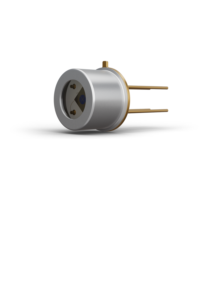
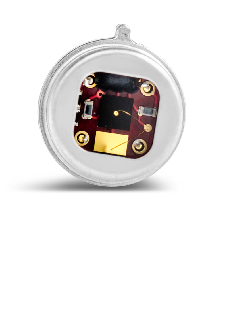
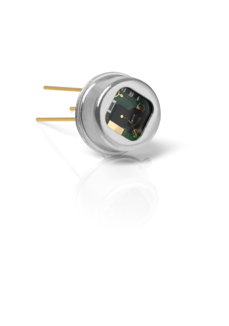
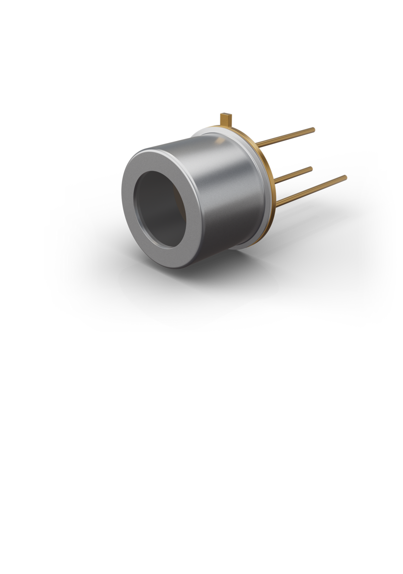
Pyroelectric detectors are unique from other thermal detectors in that they have no DC or CW response. In order to produce an output they must experience an optically (IR) induced change in their temperature. This is classically accomplished by pulsing or chopping the input energy. The minimum chopping or pulse frequency is determined by the device’s thermal time constant which is analogous to the heat leak rate. This is typically on the order of 10 to 300 msec and can be specified. If the detector is configured for very high power applications the heat generated by the absorbed power must be dissipated and thus in this case the time constant is greatly reduced by heatsinking the element.
These IR detectors are actually charge generators where the charge produced is a function of their temperature change. However the charge is quickly dissipated due to the element’s thermalization (back to ambient) caused by the heat leaking away (time constant). The charge produced by the change in temperature as a function of time (Coul/sec) gives rise to a current which is a function of the power absorbed by the element. Thus the device produces a current response by which it is specified (A/W). For this reason these are usually modeled electrically as current sources in parallel with their own capacitances.
As capacitors they are high impedance devices and thus act as integrators of the voltage produced by their thermally induced current. Thus the voltage produced as a function of time is .
In order to resolve a pulse and measure its power (Watts) the detector’s electrical time constant must be reduced which is accomplished by the addition of a shunt resistance (Rl) whose value is a function of the pulse frequency.
In general the electrical time constant should be at least 1/10 of the pulse width.
The output voltage will be:
Where Zeff is the total impedance of the detector and Pd is the input optical power.
Note that the input impedance of the measuring instrument and the capacitance of any cabling need to be
considered part of the Zeff. Often a transimpedance amplifier is used to better couple the detector to the
measuring instrument.
In application the impedances required to resolve the pulse are so small that the voltage produced is very small and may approach the limit of the signal to noise of the measuring equipment. In this case the total energy in the pulse is measured in Volts/Joule.
BILD
The output pulse will be look as below:
SKIZZE
The amplitude of the pulse is the total energy in the detected heat pulse. The average power (Watts) in the pulse can be calculated knowing the V/J and the pulse width. One of the drawbacks to using these or any other detector for measuring laser pulses is the damage induced by these short high energy pulses where the average power is low but the peak power is enough to damage the element. For this case very low cost devices based on other much cheaper materials are used and are considered ablative as the replacement cost is very low.

Click here
IR Detectors
MANUFACTURED BY LASER COMPONENTS
Downloads
Beyond Borders
LASER COMPONENTS Germany - Your competent partner for optical and optoelectronic components in Germany.
Welcome to LASER COMPONENTS Germany GmbH, your expert for photonics components. Each product in our wide range of detectors, laser diodes, laser modules, optics, fiber optics, and more is worth every Euro (€/EUR). Our customized solutions cover all conceivable areas of application: from sensor technology to medical technology. You can reach us here:
Werner-von-Siemens-Str. 15
82140 Olching
Deutschland
Phone: +49 8142 2864-0
Email: info(at)

