Precision Measurements of Cable Assemblies Ensure High Quality
With the increase in the popularity of fiber-guided laser systems the quality requirements of the market are also increasing. To ensure the high quality of assembled fibers, LASER COMPONENTS has continuously expanded its measurement capabilities in recent years. The company’s laser laboratory possesses numerous equipment to verify and document that the delivered products meet the specifications required by the customer.
Laser Power Measurement
Beyond Borders

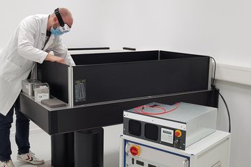
In the laser laboratory, the functionality of high-power assemblies is tested by subjecting them to stresses similar to those encountered in daily use. The diode laser systems used for this purpose cover two configurations that are frequently used in industry: Fibers that are 200 µm in diameter and larger are tested at a wavelength of 980 nm for cw laser powers of up to 130 W. In addition, tests with 50 W cw are also possible for 100 µm fibers. The laser used for this emits at a wavelength of 914 nm.
For attenuation measurement, the outgoing beam is detected using a laser power meter to determine whether optical losses have occurred during transmission and whether the fiber can withstand the load from the laser. Temperature sensors on the connectors can also be used to detect heat that indicates cladding modes or other damage.
Figure 1: Laser power measurement station
Fiber End Face Inspection
Beyond Borders

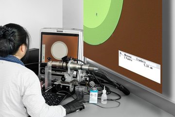
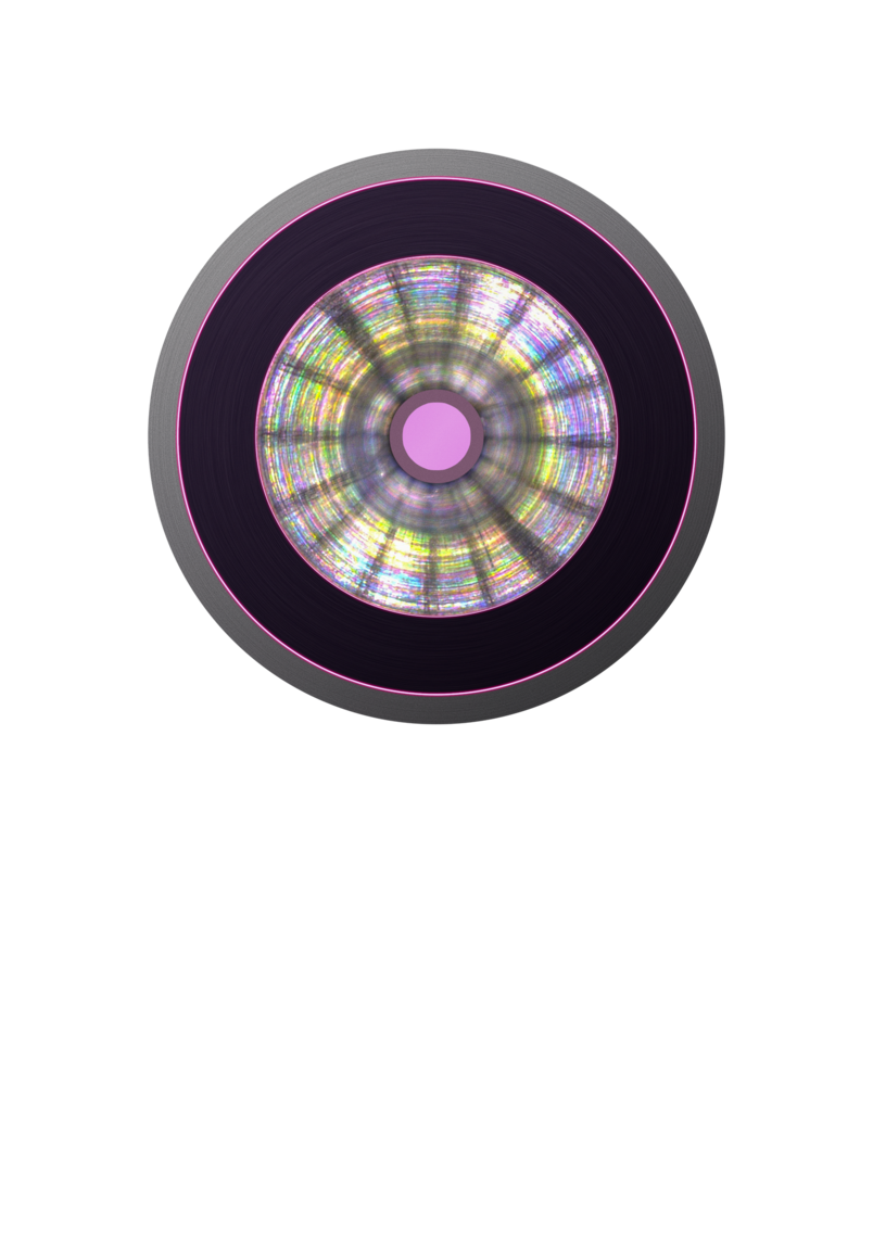
A perfectly clean fiber end face is an indispensable quality criterion. When transmitting high optical power, even the smallest particles – those just a few µm in diameter –can destroy the fiber. LASER COMPONENTS inspects all end faces without exception using a digital measuring microscope during a final quality check. By selecting a magnification of 300x, even the tiniest contaminations can be detected.
For the evaluation of uncoated fibers, the company follows a strict zero-defect policy. When inspecting fiber end faces with anti-reflective coatings, standards for laser optics are used, as defined by the ISO standard 10110. The specification 5/C3x0.005 applies, which means that an imperfection may not occur at a grade number higher than 0.005. The sum of the grade numbers of all imperfections may not exceed 3x0.005. The grade number is defined as the square root of the area of the imperfection.
Figure 2: Fiber end face inspection with digital measuring microscope (magnification factor of 300)
Centricity Measurement
Beyond Borders
The centricity of the fiber within the connector is a decisive criterion for avoiding unwanted cladding modes. Only if the fiber has been precisely aligned can the assemblies be easily exchanged by plugging and unplugging. As part of the outgoing goods inspection, the centricity of each assembly is checked. A maximum deviation of 10 µm between the fiber center and the ferrule center is tolerated as a standard. However, it is also possible to achieve an accuracy of <5 µm upon request.
Measurement of the Numerical Aperture of Multimode Fibers
Beyond Borders

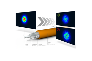
The numerical aperture (NA) of an optical fiber describes the degree of opening of the cone-shaped light bundle emerging from the end face of the fiber. It corresponds to the sine of the divergence angle.
After transmission through the fiber, the divergence of the exiting beam should ideally correspond to that of the coupled beam. However, this can only be achieved with single-mode fibers, which always produce a beam with an ideal Gaussian profile.
Figure 3: Setup of an optical fiber in the NA measuring station. Good (top) and poor (bottom) NA preservation.
In multimode fibers, the output beam always deviates from the ideal shape because the individual modes mix and overlap. LASER COMPONENTS aims to keep this deviation as small as possible. That is, 95% of the outgoing power should still have the same beam parameters as the coupled beam.
For control and documentation purposes, LASER COMPONENTS has specially developed its own NA measuring station. The numerical aperture is determined by measuring the encircled angular flux (EAF). These tests can be carried out for any kind of multimode fiber in the LASER COMPONENTS portfolio.
Competence in Fiber Technology
Beyond Borders
With these measuring devices LASER COMPONENTS ensures that only the assemblies that meet the customer’s specifications and satisfy the company’s highest quality standards are shipped. When implementing individual fiber optic solutions, our production experts capitalize on their propensity for precision and their comprehensive technical know-how.
For special requirements, our in-house R&D team develops innovative solutions such as fiber tips and individual coatings for fiber end faces.
Product Overview
Beyond Borders

Click here
Downloads
Beyond Borders

